Before you start
Building P6 is easy if you’re used to soldering. If you’re new to this, I recommend reading this tutorial.
Please also check this page that will help you identify bad solder joints.
Take your time, read this guide twice before warming your soldering iron.
Work in a clean place with enough space to do things properly.
Take your time and be patient, you will have a fully functional synth if you follow this guide thoroughly , but a single little mistake can turn a few hours build into a days/weeks build.
What comes with the kit?
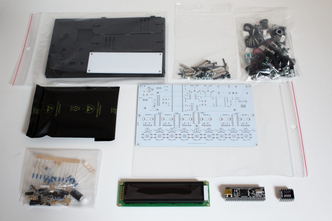
In the kit, you will find (from left to right, top to bottom):
- Acrylic case kit
- Screws and spacers bag
- Misc bag (pot, encoders, knobs, buttons, etc.)
- Active parts bag
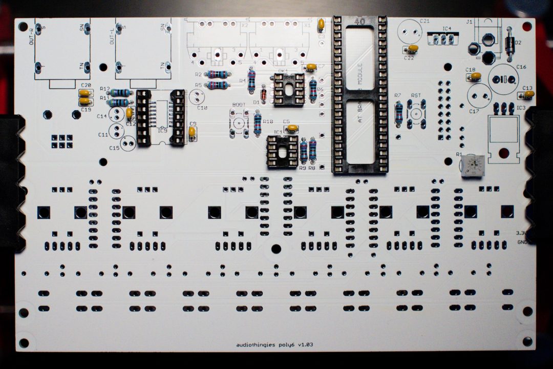
- PCB
- Passive bag
- LCD screen
- BRAIN40 board (CPU)
- Soldered DAC
Step 1 – LCD pin headers
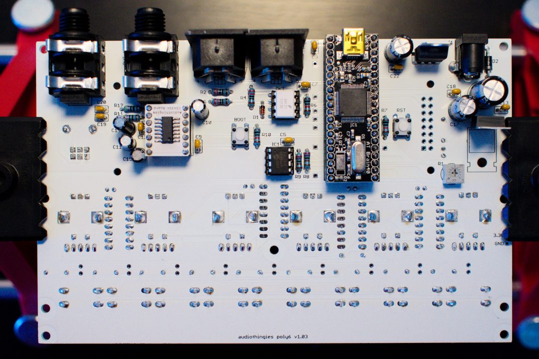
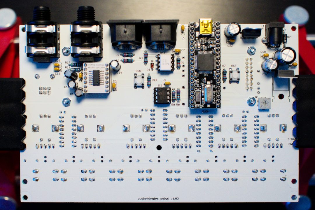
We will start our soldering with the bottom side of the PCB first.
Based on user feedback, before soldering anything else, it might be a good idea to solder the LCD pin headers now, as this will ease the build later on.
So please check Point 15. Solder only the pin headers, do not install nor screw the LCD yet.
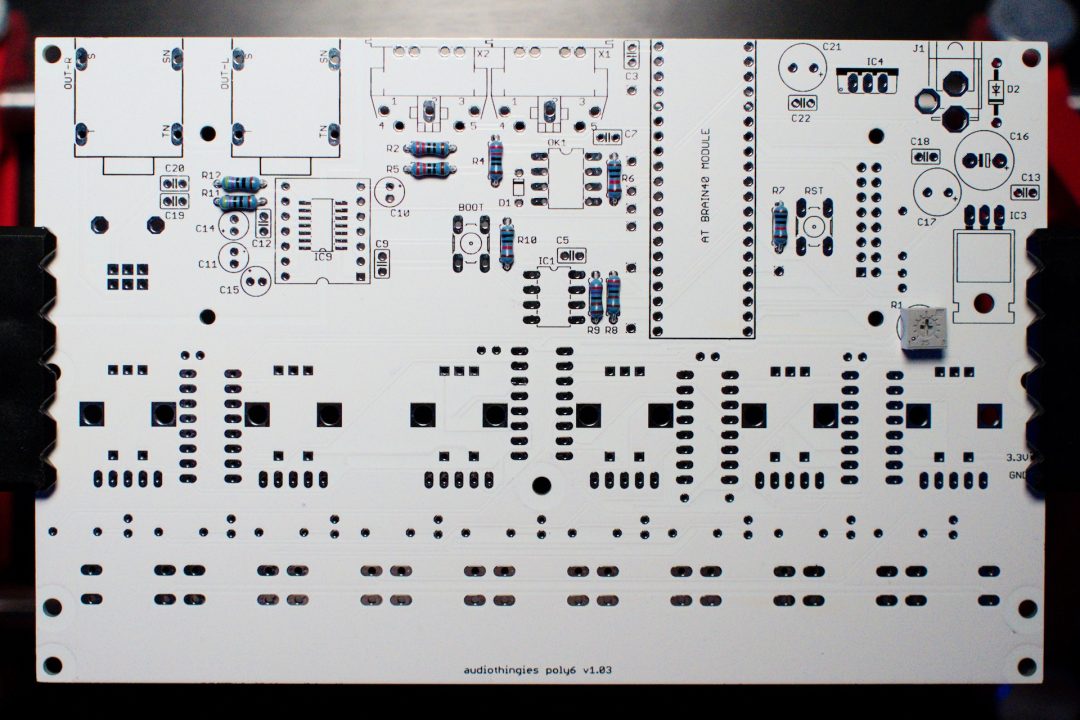
Step 2 – Resistors
Solder the following resistors:
– R2, R4, R5 (220 ohms : Red Red Brown Brown or Red Red Black Black Brown)
– R6, R7, R10 (10k ohms : Brown Black Orange Brown or Brown Black Black Red Brown)
– R8 and R9 (2.7k ohms : Red Violet Red Brown or Red Violet Black Brown Brown)
– R11, R12 (470 ohms : Yellow Violet Brown Brown or Yellow Violet Black Black Brown)
– R1 (lcd contrast pot)
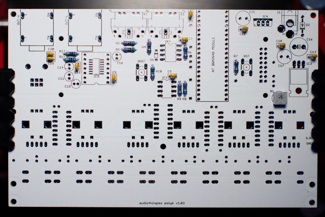
Step 3 – Non polarized caps
Next add the following ceramic caps
– C3, C5, C7, C9, C12, C13, C18, C22 (100n : marked 104)
– C19, C20 (2200p : marked 222)
Step 4 – Diodes
These are polarized. Pay attention to the orientation. They are 2 diodes :
– D1 (1N4148) – black ring point to the MIDI connector
– D2 (1N4001) – grey ring point to C16
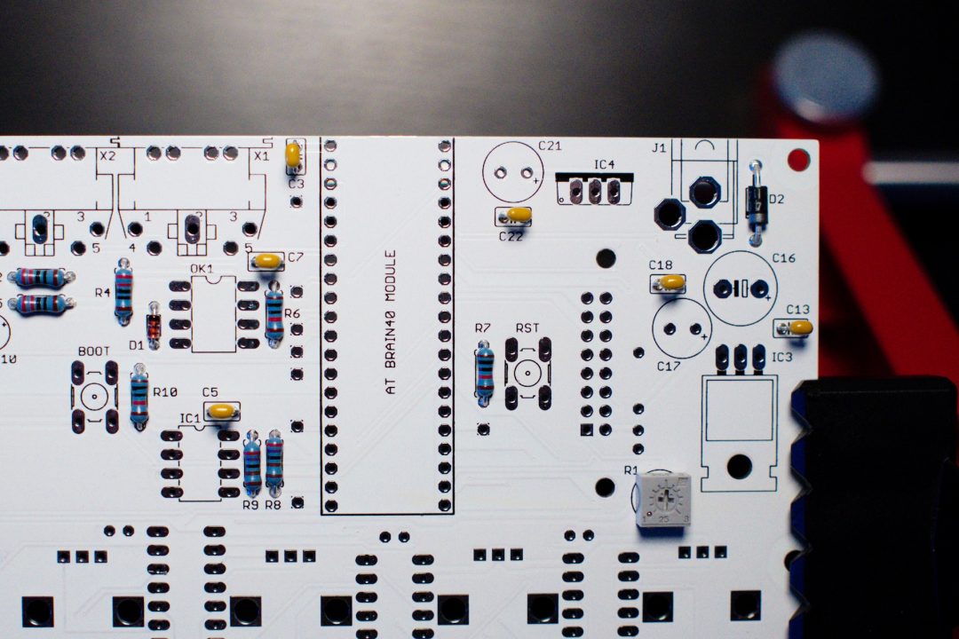
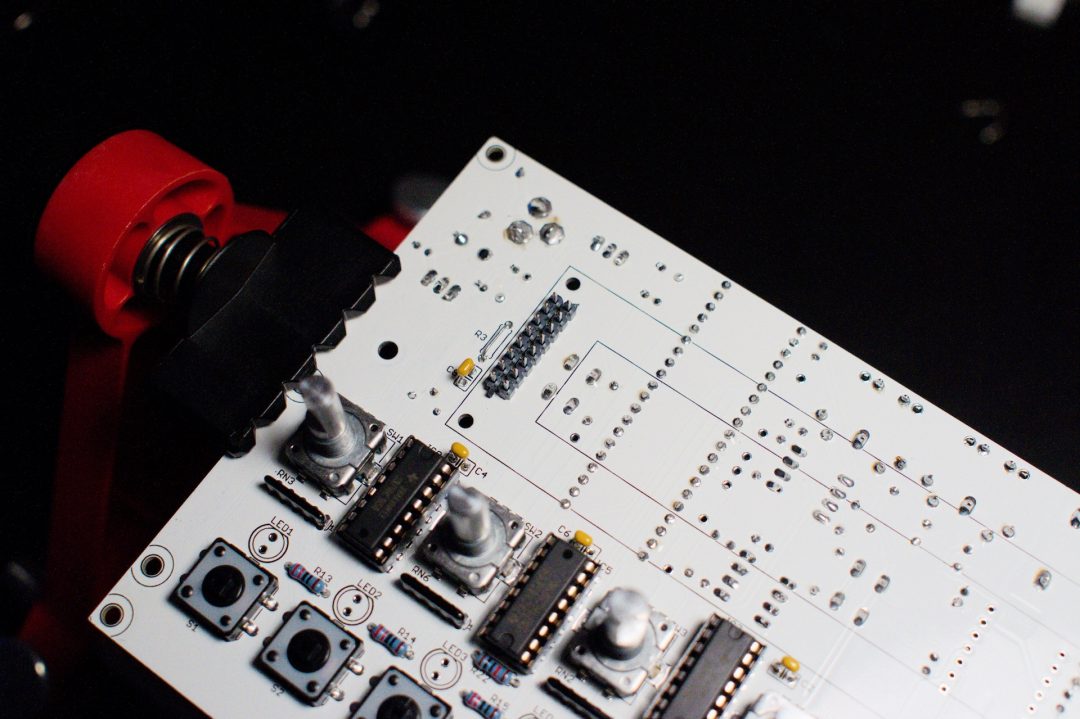
Step 5 – IC sockets
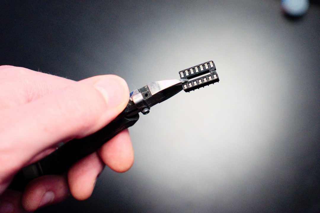
First install the DAC 14-pin socket.
To do so, you need to cut a standard 14-pin IC socket into 2 pieces:
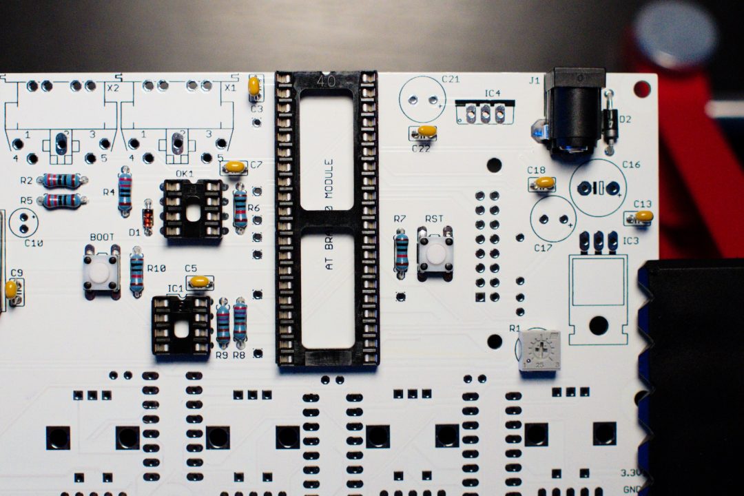
Then install and solder the following IC sockets
– AT BRAIN MODULE (40-pin)
– IC1, OK1 (8-pin)
– DAC 14-pin socket
Step 6 – Switches & DC connector
Install the 2 switches first:
– BOOT, RST
Then the DC connector:
– J1 : Solder one leg, adjust the connector into the right position, then solder the other legs.
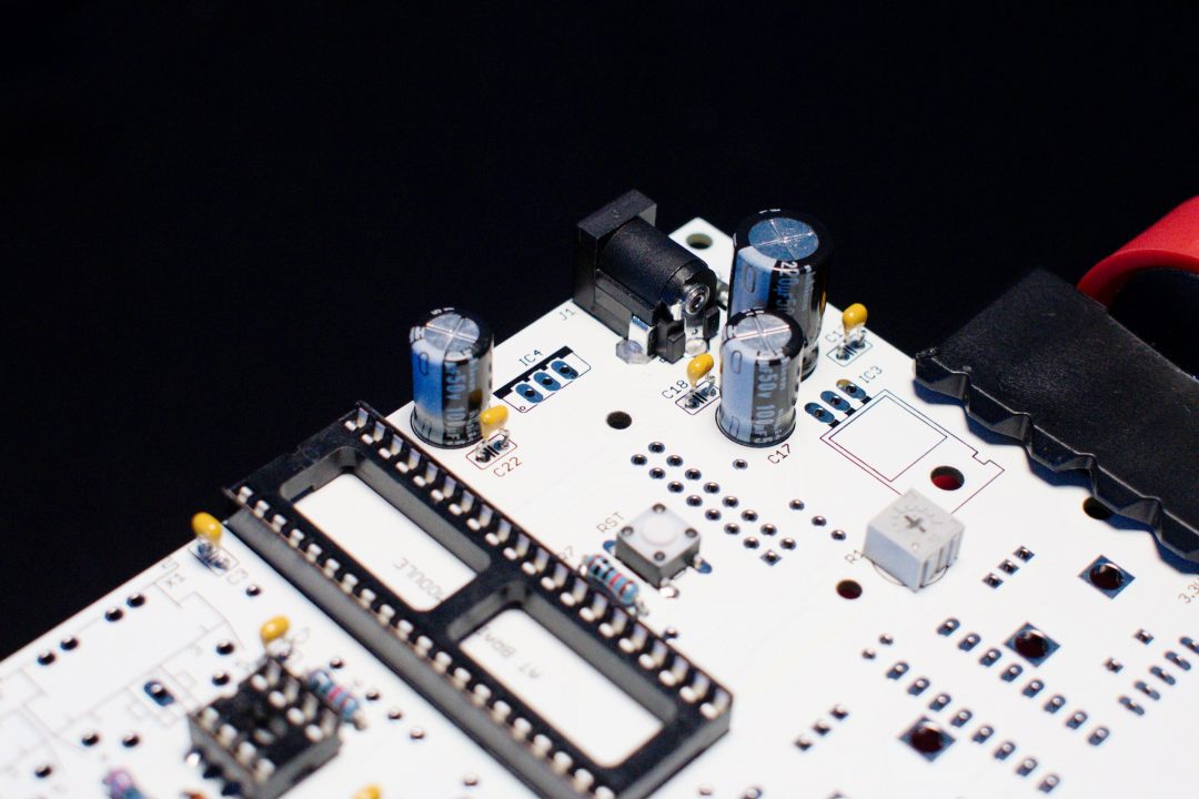
Step 7 – Polarized capacitors
The white stripe on the side of the electrolytic capacitors indicates the negative lead. The negative lead is the shortest one. This means the longest lead (positive) must go in the hole marked with a plus sign. Quite logical 😉
Power supply section (right side of board):
– C17, C21 (100u)
– C16 (220u)
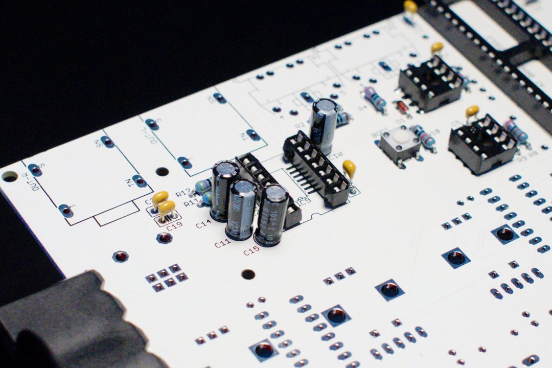
Audio section (left side):
– C10, C11, C14, C15 (2.2u)
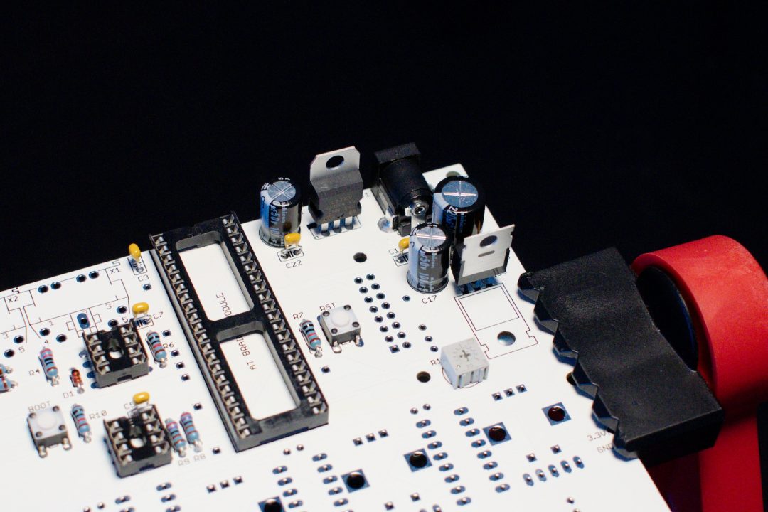
Step 8 – Voltage regulators
The board needs 2 different voltages, 5V and 3.3V.
Install the 2 voltage regulators
– IC3: 7805 “metal” plate points to the bottom of the board.
– IC4: 1117V33 or LD33CV “metal” plate points to the top of the board
Do not invert the 2 voltage regulators, they look the same but they are not the same!
At this point, look for short cuts between +5V, +3.3V and ground.
GND and 3.3V test points are available at the right side of this PCB side. You will find a 5V test point at pin 3 of 7805 (IC3), this is the pin located near C17.
Check cap polarity again.
If OK, without any IC’s inserted, power the board and control the voltages using the same test points. You should read 5V and 3.3V.
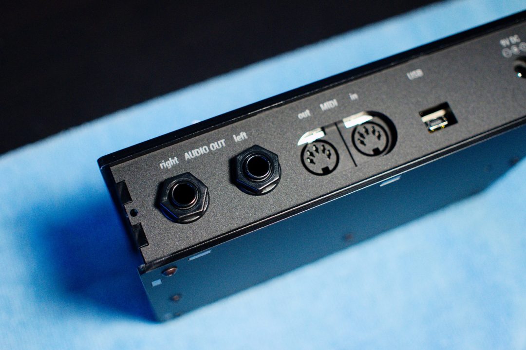
Step 9 – MIDI/Audio connectors
– X1, X2
– OUT-L, OUT-R
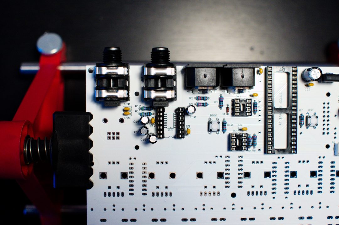
Before going any further, look at all your solder joints.
Reheat if necessary.
It is very important to look at all these, especially the ones that will be hidden by the LCD screen. You should also try to cut their legs as flat as possible to avoid shorts with the LCD screen.
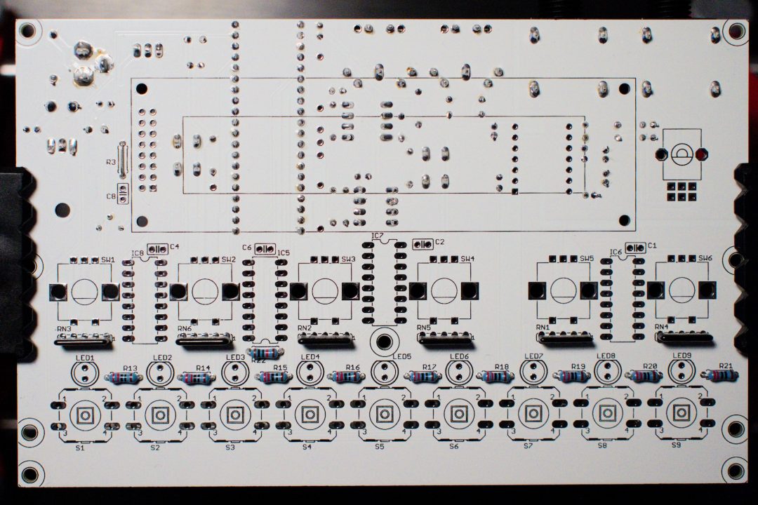
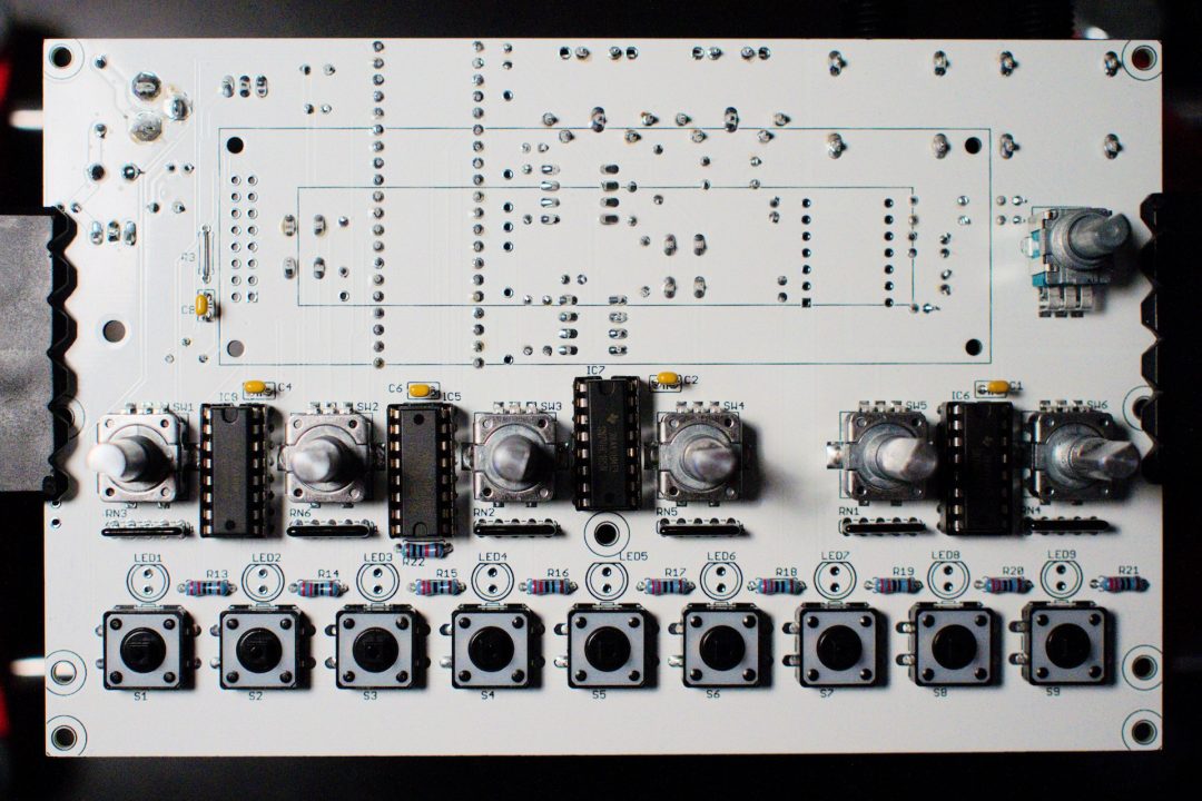
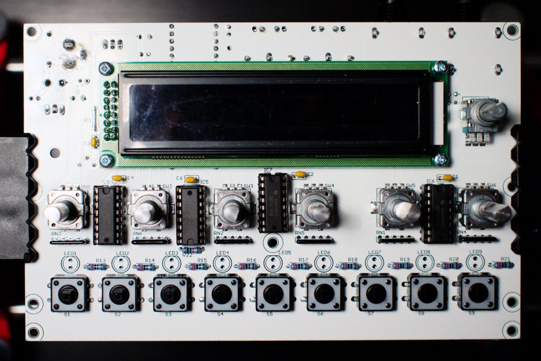
Bottom side is finished, let’s continue with the top side of the board :
Step 10 – Resistors
Solder the following resistors
– R13 to R21 (220 ohms : Red Red Brown Brown or Red Red Black Black Brown)
– R22 (10k ohms : Brown Black Orange Brown or Brown Black Black Red Brown)
– R3: if you use the lcd provided in the kit, install a jumper in R3 (not provided in the kit, use a lead of a component you just cut)
– RN1 to RN6: resistor networks. These are polarized. The side with a white stripe points to the right of the pcb.
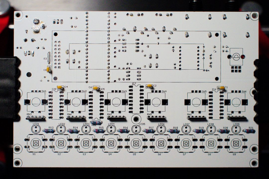
Step 11 – Non polarized caps
– C1, C2, C4, C6, C8 (100n : marked 104)
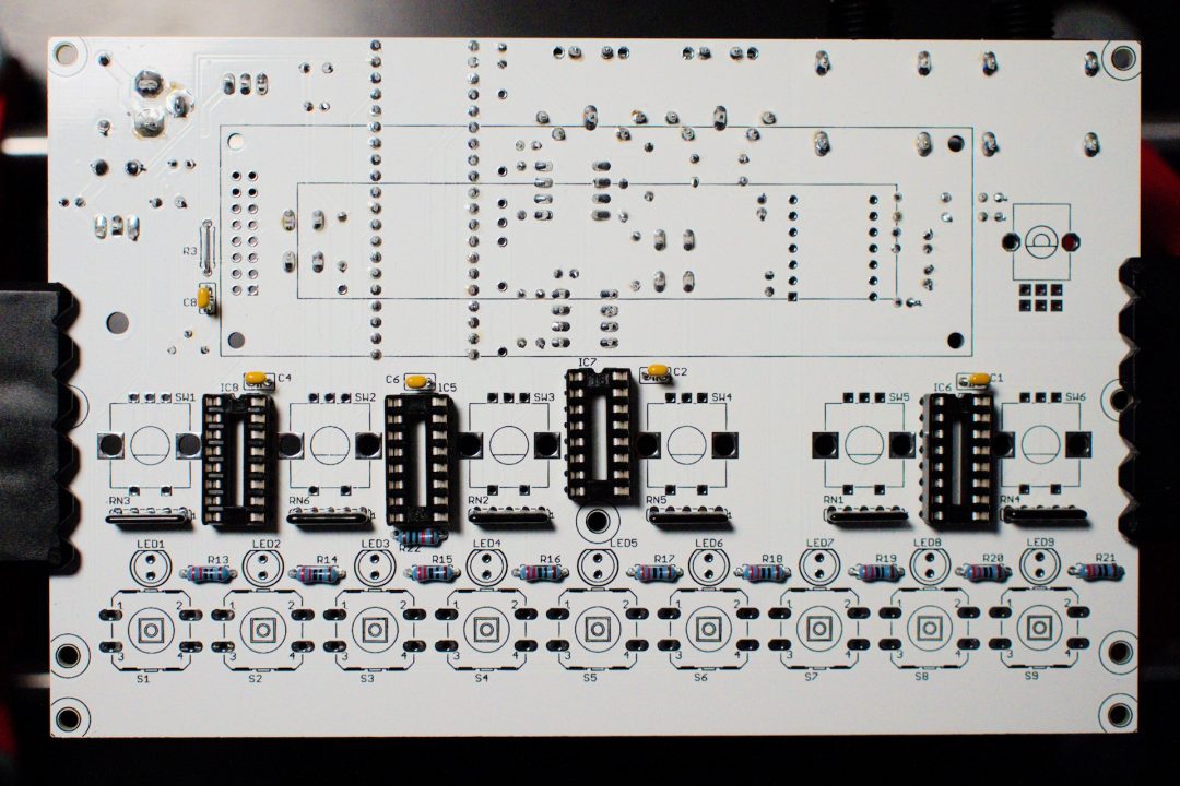
Step 12 – IC sockets
– IC5, IC6, IC7, IC8 (16-pin) – pay attention to the chip orientation
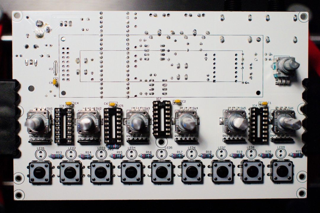
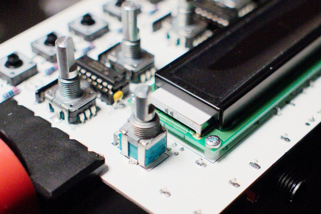
Step 13 – Switches / Encoders / Pots
– S1 to S9
– SW1 to SW6
– stereo volume pot
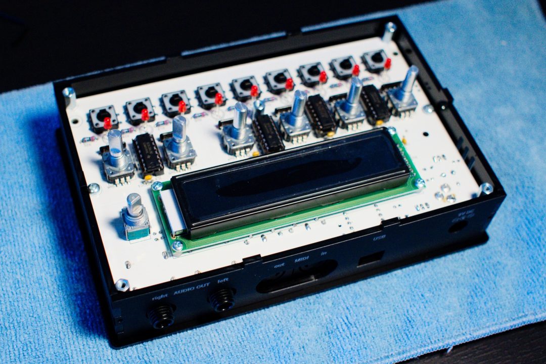
Step 14 – First test
Now, check all your solder joints.
Control voltages (GND, 3.3V, 5V) (see point 8)
If everything’s fine, insert all IC’s (pay attention to the orientation).
IC5 : 74HC595
IC6 to 8 74HC165
Insert the Brain 40 module.
The Brain 40 module included in the kit is already tested and programmed.
Install 6N137 (OK1) and the 24LC512 EEPROM (IC1).
Finally insert the CS4354 DAC boards.
Power the board with a 9V DC adapter.
Measure the voltages on the DAC.
Here is the pin numbering on the DAC (click to enlarge)
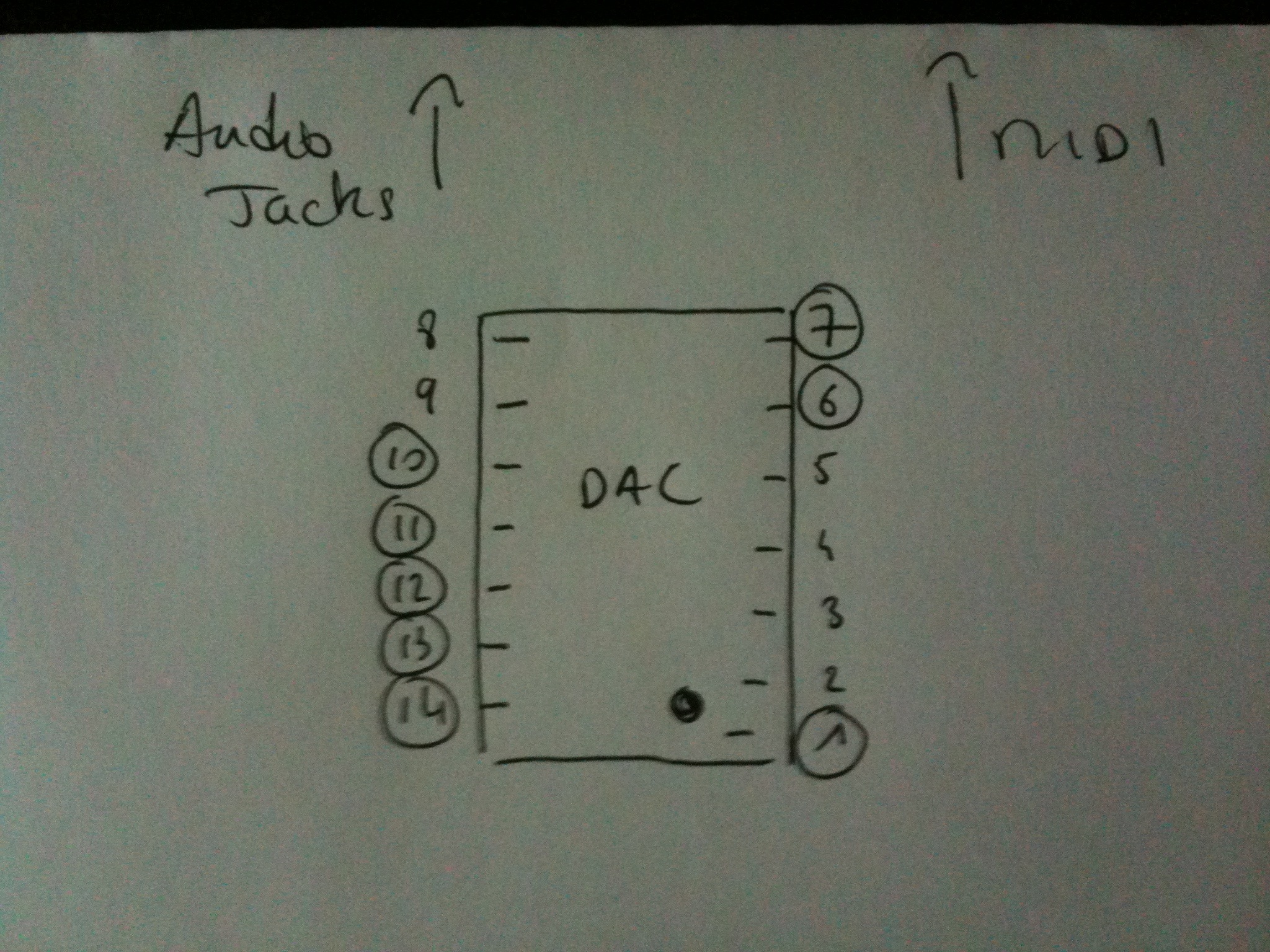
Measured values on my prototype are :
- 1 : 3,3V
- 6 : 0V (check continuity with GND)
- 7 : 3,5V
- 10 : 0V (check continuity with GND)
- 11 : 5V
- 12 : 2,55V
- 13 : -2,4V
- 14 : -4,8V
If you do not have these voltages, double check your soldering on the DAC pins and surrounding caps.
Then, if all good, connect a MIDI keyboard (channel 1) to MIDI IN socket (the one that is next to the mini-USB port), audio outs to a mix table.
Play a few notes, you should hear a basic sound responding to pitch (don’t forget to turn the pot volume up – I always do).
If you have the sound, then everything’s fine. Do not try to load any presets as this will not work yet.
If not, then triple check your voltages, solder joints, IC orientations until you get a sound.
DO NOT GO BEYOND THIS POINT IF YOU HAVE NO SOUND OR WRONG VOLTAGES – ASK FOR HELP ON THE FORUMS
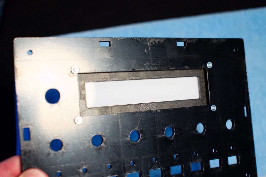
15 – LCD
Solder the pin headers to the boards (longest lead thru the pcb).
Place and screw the LCD screen with the included M2.5x10mm screws and nuts, with a 3mm nylon spacer between the LCD and the board.
Do not solder the lcd yet.
Check if you still have sound. If not, you may have a short between the board and the lcd.
If everything’s fine, solder the LCD.
Power the board again, you should have the LCD working (check the contrast pot at the back of the board – I always forget) and sound while playing notes on a MIDI keyboard.
Buttons/encoders should work too, but you won’t be able to load presets, as they are not written to EEPROM yet. This is normal behavior.
16 – LEDS
To help positioning the LEDs, you need first to mount the case top panel. To mount the top panel, you need to mount the spacers:
– 5 x 10mm MF spacers (top) + 5 x 25mm FF spacers (bottom) on the 4 corners and above LED5.
– 2x M3 screws (top) + 2 x 25mm FF spacers (bottom) on the left of encoder 1 and on the right of encoder 6.
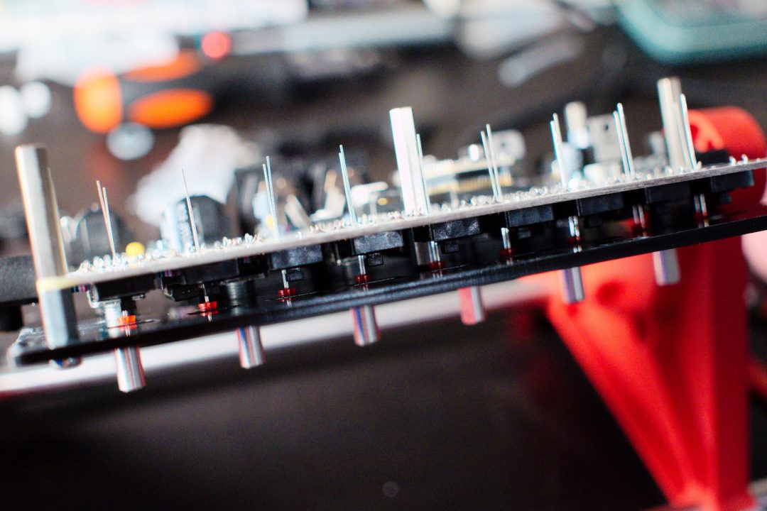
Then insert the LEDs without soldering them. The longest lead (positive side) is on the side of the switch.
Re-check polarity, longest lead (positive side) is on the side of the switch, not the encoder.
Screw the top panel with M3 black hex screws.
Return the unit.
Slip the LEDs into their respective holes and solder them. This ensures the LEDs fit perfectly in their respective holes.
Power the board, you should have LCD working, LEDs working and sound output.
17 – Case
Unmount top panel.
Remove the protection sheets from the panels.
You may need to clean the engraved plexiglas parts (due to engraving residue, a slightly humidified microfiber will do, I personally wash them with water and a small amount of dish soap).
Mount the 2 x PET foil in sandwich between the top panel and the 2mm acrylic LCD window (do not forget to remove the protection sheets)
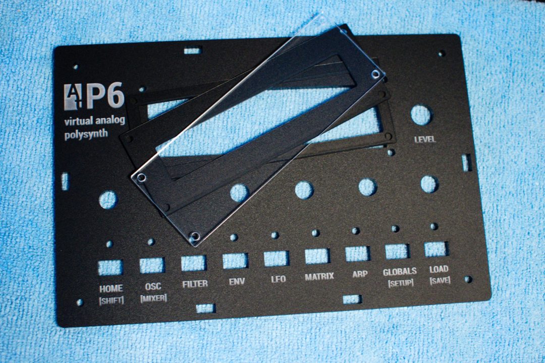
Screw them with 10mm M2.5 screws and nuts :
Place the bottom panel and the 3 sides panels like this:
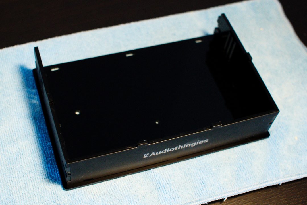
Place the PCB and the bottom-side panel
Place the top panel. Screw it with 4 M3 black hex screws.
Carefully return the unit.
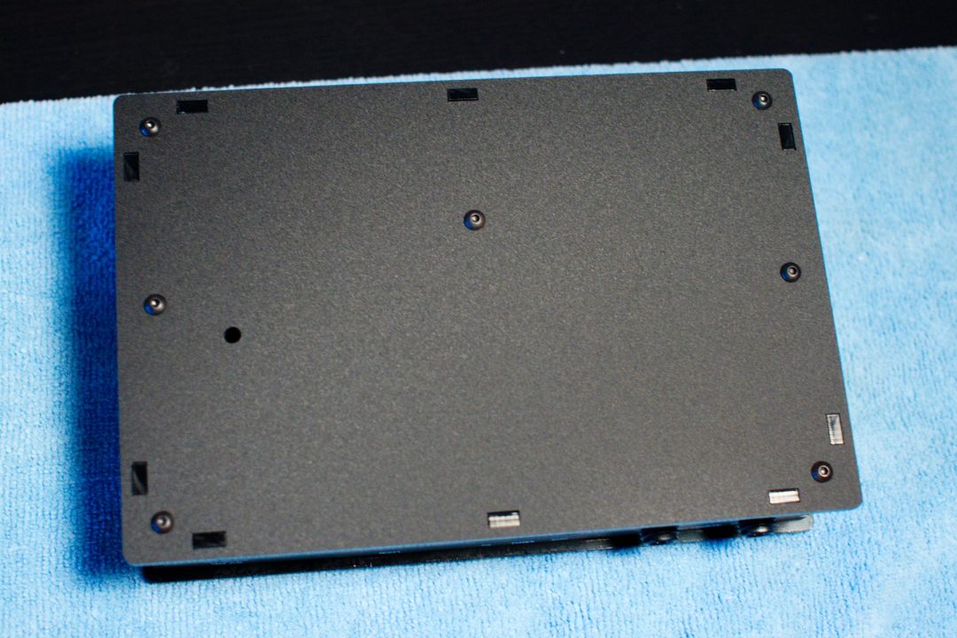
Screw the bottom panel with 7 black hex screws.
Install audio connectors nuts
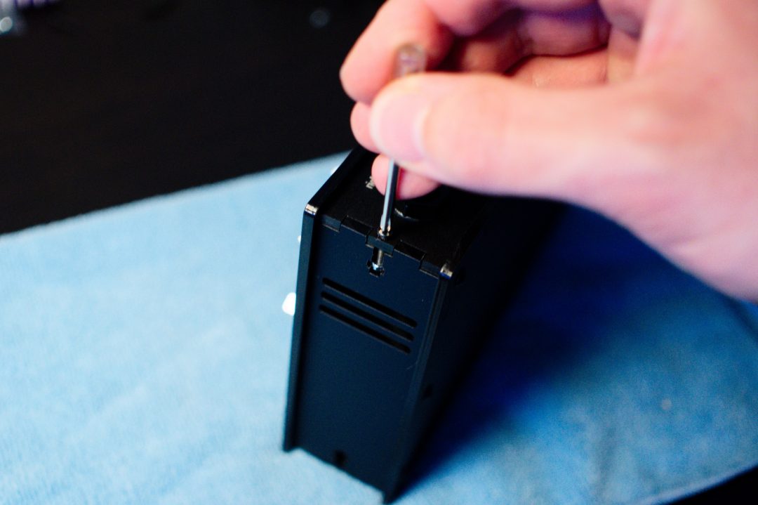
Secure the side panels with M2.5x12mm black screw and nut (x4)
Final step: install the 4 rubber feet.
NOTE: To assemble the square enclosures, we suggest this order:
- Top panel, add knobs
- Bottom panel, add rubber feet
- Rear panel (the one with the connectors)
- Side panels
- Front panel
18 – Format EEPROM
Power the unit while pressing buttons 2 and 8.
A screen will appear asking for an EEPROM Format.
Press Load to confirm. This will also write a few presets to get you started.
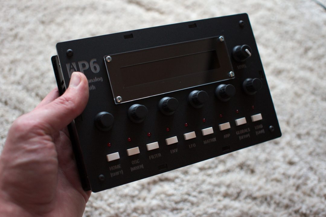
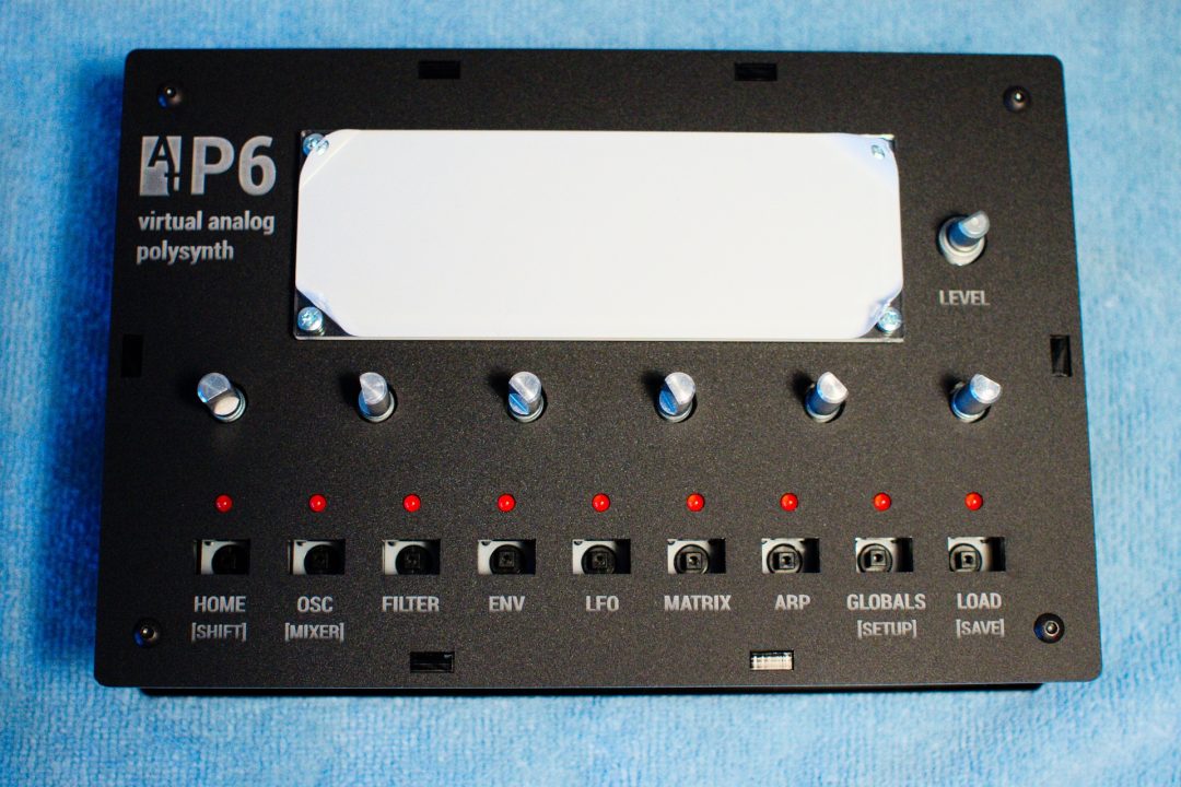
You’re done! Enjoy your P6
Now, and only now, you can update the firmware.